Fiber Optic Technical Information & Documentation
- - 4 min read
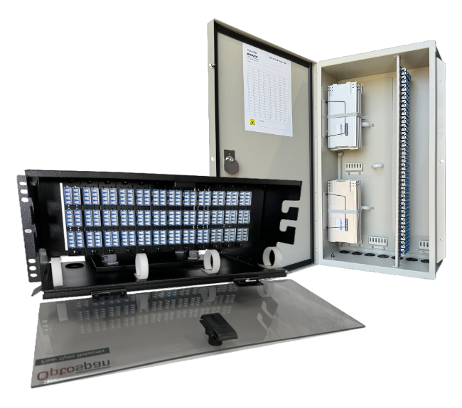
Modern networks do not stay small for long. As data needs rise, teams need a clean way to add more links, protect cable paths, and keep future upgrades simple. That is where design matters more than many people expect. A well-planned fiber optic patch panel does more than hold connections in one place. Read more...
- - 5 min read
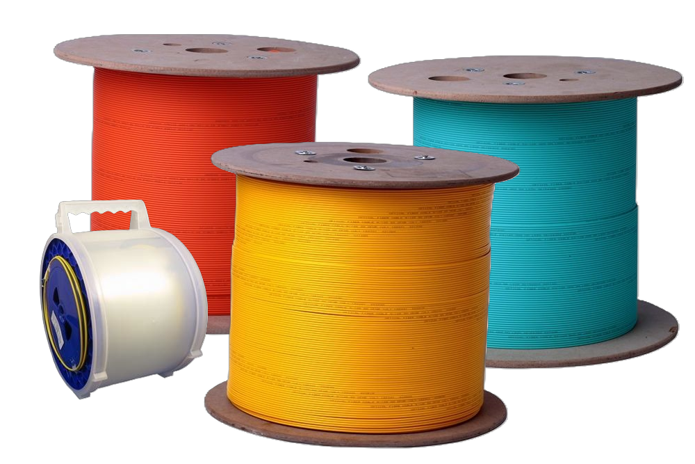
Modern networks carry more traffic than ever before. Data moves between offices, server rooms, cloud systems, security tools, and connected devices every second. As this demand rises, network design must support more links in less space without making future upgrades harder. Read more...
- - 4 min read
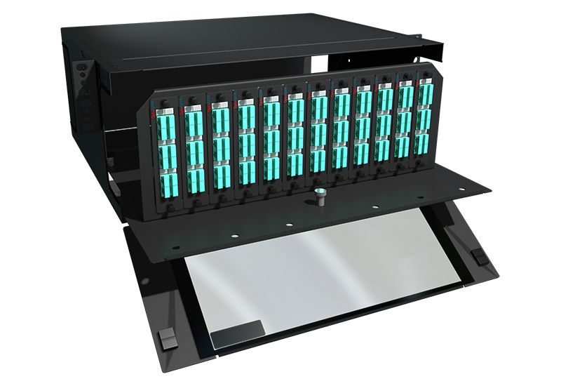
A fiber network can perform well only when the physical layout supports clean routing, easy access, and room for future change. That is why panel design should never be treated like a small detail at the end of a project. Read more...
- - 5 min read
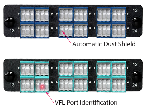
Modern data centers depend on clean, stable, and well-planned fiber links to support fast network traffic and steady uptime. A small mistake at the end of a fiber line can lead to signal loss, link failure, or slow troubleshooting when teams need quick answers.
That is why termination work deserves close attention from the start of a project. At SanSpot, the focus on strong fiber connectivity solutions reflects a simple truth. Good installation habits, clear planning, and careful testing make a real difference in daily network performance and long-term reliability. Read more... - - 4 min read
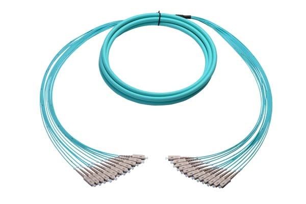
In many network setups, cables can slowly turn into a quiet problem. They sit behind racks, often unnoticed, yet they affect how well everything runs. When there are too many separate patch cables, the space feels tight and messy.
This is where a fiber breakout cable finds its place. It is not a complex idea, yet it solves a real issue. For teams working with fiber systems, it brings some order. In this blog, we will talk about its uses, its simple benefits, and how it fits into everyday network work. Read more...
- Patch Panel Designs for Scalable Network Growth
 July 6, 2026
 - How Bulk Fiber Optic Cable Supports High-Density Network Growth
 July 6, 2026
 - MPO Panel Design Tips for Scalable and Efficient Fiber Networks
 July 6, 2026
 - Best Practices for Fiber Terminations in Modern Data Centers
 July 1, 2026
 - Understanding Fiber Breakout Cable Uses and Benefits
 July 1, 2026