What Is the Difference Between MTP and MPO Cables?
MTP and MPO connectors will mate with each other and carry the same fiber counts, but they are not the same connector, and speccing the wrong one for a high-density or high-speed deployment can mean higher insertion loss, failed compliance testing, or a polarity mismatch you only discover after the cable is run.
Before you order, you need to confirm:
- Connector gender: Pinned (male) or unpinned (female)
- Polarity method: Method A, B, or C
- Fiber count: 8, 12, or 24 fibers
- Fiber type: Single-mode (OS2) or multimode (OM3/OM4/OM5)
- Loss budget: Whether a standard MPO assembly or a high-performance MTP/MTP Elite® assembly provides the optical tolerances your link budget requires
This post is a spec-check filter, not a general overview. If you are mid-project and need to confirm which connector to order, this post walks you through the MTP vs MPO differences that actually matter at the rack.
We will look at:
- What MPO and MTP connectors are, and where the distinction comes from
- The mechanical differences between them: ferrule, pin clamp, housing
- Compatibility: Can MTP and MPO mate with each other?
- Polarity methods (Type A, B, C) and why they determine your assembly order
- MTP vs MPO Comparison Table
- Which Connector Fits Your Deployment?
- SanSpot product picks matched to deployment type
- FAQ
What Are MPO and MTP Connectors?
MPO is an industry-standard multi-fiber connector interface covered by IEC 61754-7 series and TIA-604-5 (FOCIS 5) requirements. Any connector manufacturer can build an MPO-compliant connector as long as it meets the standard.
MTP is a registered trademark of US Conec. MTP connectors are MPO connectors; they meet the same IEC and TIA standards, but they are manufactured to tighter tolerances than the base MPO specification requires.
The floating ferrule design, precision-machined pin clamp, and improved housing geometry are the specific engineering choices US Conec made to push insertion loss below what standard MPO typically delivers. These differences are central to understanding MTP vs MPO when selecting connectors for a specific network.
Key Takeaway: Every MTP connector is an MPO connector. Not every MPO connector is an MTP connector. They will physically mate with each other, but they do not perform identically under tight link budgets.
Mechanical Differences: Where MTP and MPO Actually Diverge
The visual difference between an MTP and a standard MPO connector is nearly zero. The engineering difference is significant enough to affect insertion loss in high-density or high-speed deployments.
MT Ferrule and Floating Ferrule Design
Both connectors use an MT (Mechanically Transferable) ferrule, the precision component that aligns the fiber ends at the mating interface. MTP connectors use a floating ferrule design that helps maintain fiber contact integrity during mating. Generic MPO implementations can use different ferrule designs, so the exact construction depends on the connector manufacturer and product grade.
This matters because real-world mating surfaces are rarely perfect. A floating ferrule maintains face-to-face contact across minor angular misalignments that a fixed ferrule would leave as an air gap, and air gaps create insertion loss.
Pin Clamp: Plastic vs. Precision Metal
Guide pins (also called alignment pins) lie inside the male connector and engage with holes in the female connector to align the two ferrules precisely at mating. The pin clamp holds these guide pins in position.
Standard MPO connectors use a plastic pin clamp. MTP connectors use a metal pin clamp. Metal holds tighter tolerances over repeated mate/demate cycles. In a data center environment where patch panels are reconfigured regularly, a plastic pin clamp degrades faster and introduces positional variation over time.
Removable Housing and Push-Pull Tab
Many MTP connector designs use removable housings that support rework and, on compatible configurations, field pin or polarity changes without replacing the entire cable assembly. This matters for field repair and for changing a connector from male (pinned) to female (unpinned) without cutting the cable.
Standard MPO connectors do not offer this. The housing is fixed. A gender change means cutting and reterminating.
| Performance level | Representative insertion loss |
|---|---|
| Standard MPO | Up to 0.75 dB |
| Low-loss MPO/MTP | Up to 0.35 dB |
| MTP Elite | Up to 0.20 dB – 0.25 dB |
Buyer takeaway: If your deployment involves frequent reconfiguration, a high-density rack, or a loss budget tighter than 0.75 dB per connector, the mechanical differences between standard MPO and MTP are not cosmetic; they affect whether the link passes testing.
MTP and MPO Compatibility
Yes, MTP and MPO connectors are physically compatible. An MTP male connector will mate with an MPO female connector, and vice versa. The mating face geometry and guide pin spacing follow the same IEC 61754-7 standard.
What compatibility does not mean: mating an MTP with a standard MPO does not give you MTP-level insertion loss.
Compatibility also does not resolve polarity. Two connectors that physically mate can still deliver a signal to the wrong fiber strand if polarity is not matched at both ends and at every cassette or patch panel in the path. Polarity is addressed in the next section.
Polarity Types A, B, and C: Why It Determines Your Assembly Order
Polarity ensures that the optical transmitter (Tx) at one end of the link maps directly to the optical receiver (Rx) at the opposite end. Multi-fiber arrays cannot simply be flipped like standard duplex LC patch cords.
- Method A (Straight): Use straight-through fiber positioning. The required key orientation and duplex patching depend on the complete cabling architecture, including the transceiver, cassette, adapter, and patch-cord arrangement.
- Method B reverses the fiber positions from one end of the array to the other.
- Method C reverses each adjacent fiber pair rather than reversing the entire fiber sequence.
What you need to confirm before ordering:
- What polarity method is your existing infrastructure built on?
- Are your patch cords Key-Up to Key-Down or Key-Up to Key-Up?
- Does your transceiver module specify a polarity requirement?
- If using cassettes, what polarity type are the cassettes, and do they match the trunk?
Mixing polarity methods creates a working physical connection with the wrong signal path. The link will not pass traffic. This is one of the most common causes of "the cable is in, but the link is down" in new high-density installations.
Full MTP vs MPO Comparison Table
| Spec | Standard MPO | Standard MTP | MTP Elite® |
|---|---|---|---|
| Standard/trademark | IEC 61754-7 / FOCIS 5 | IEC 61754-7 + US Conec | IEC 61754-7 + US Conec |
| Ferrule | Standard / Fixed MT | US Conec Floating MT | Floating MT (Ultra-low tolerance) |
| Pin clamp | Molded Plastic | Precision Stainless Steel / Metal | Precision Stainless Steel / Metal |
| Housing | Fixed | Removable | Removable |
| Insertion loss (max) | ≤0.75 dB | ≤0.35 dB | ≤0.20 dB |
| Return loss (UPC, min) | ≥20 dB | ≥55 dB | ≥55 dB |
| Mate/demate cycles | \~200–500 | \~1,000+ | \~1,000+ |
| Polarity support | Method A / B / C | Method A / B / C | Method A / B / C |
| Cross-compatibility | Fully intermateable with MTP | Fully intermateable with MPO | Fully intermateable with MPO |
One line on the deciding spec: if your loss budget at each mated pair is tighter than 0.50 dB, start with MTP. If it is tighter than 0.25 dB, specify MTP Elite®. Standard MPO is appropriate where the loss budget is generous and reconfiguration frequency is low.
For further reference on polarity and fiber count configurations, see MTP/MPO cable types and configurations on SanSpot.
Which Fits Your Deployment?
Choose MTP or MTP Elite® when:
- Your 100G or 400G deployment requires the performance, density, or connector configuration supported by an MTP assembly.
- The structured cabling path includes multiple mated pairs and has limited loss-budget headroom.
- Patch panels or cassettes will be reconfigured regularly.
- Your calculated link budget requires a lower-loss connector assembly with adequate margin at each mated interface.
- You need a connector design that supports field rework or removable housing, or a compatible MTP PRO configuration that supports field pin or polarity changes.
- The application has demanding requirements for connector performance, density, or serviceability.
A standard MPO assembly may be appropriate when:
- The deployment has a straightforward, short cable path with sufficient link-budget margin.
- The cabling will remain in place with little reconfiguration after installation.
- The selected MPO assembly meets the connector performance requirements of the equipment and cabling system.
- Cost is an important consideration, and the selected assembly provides the required optical performance.
Closing takeaway: Neither option is universally better. Match the connector type and performance grade to the link budget, transceiver requirements, fiber configuration, reconfiguration needs, and overall cabling architecture rather than choosing based on data rate or connector name alone.
SanSpot Product Picks by Deployment Type
Built for Harsh Environments
OptoSpan’s 12-fiber IP68-MPO weatherproof cable features 50/125 µm OM4 multimode fiber and 2-meter MPO male-to-male connectors for 40G/100G fiber links. Its ODVA-compliant sealed bayonet locking system helps protect the fiber from water, dust, chemicals, corrosive gases, and temperature extremes, making it suitable for harsh environments such as LTE, DAS, and FTTA installations.
For data center and enterprise 40G–100G (MTP-12/24):
SanSpot MTP Cables US Conec MTP connectors with metal pin clamps and floating ferrule, verified insertion loss ≤0.35 dB per mated pair. Available in 8-fiber and 12-fiber active configurations for QSFP+ and QSFP28 applications, multimode and single-mode.
High-Performance MTP Elite Connectivity
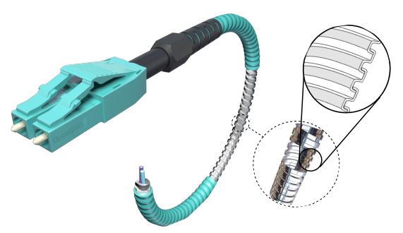
MTP Elite® Fiber Cables use high-performance MTP connectors engineered to minimize insertion loss compared with standard MPO connectors. Their tight manufacturing tolerances make them well suited for high-speed 40G and 100G fiber networks, including deployments that require additional patching and connectivity without exceeding the available loss budget.
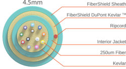
OptoSpan also uses its FiberShield design across 8-, 12-, and 24-fiber MTP Elite cables. The design adds PVC jacket material and DuPont Kevlar reinforcement to provide added protection while maintaining a flexible 4.5 mm cable profile.
40G to 10G Breakout Connectivity
OptoSpan’s QSFP+ to 4xSFP+ Active Optical Cables (AOC) provide a high-performance, cost-effective solution for 40GbE to 10GbE equipment interconnects. This 1-meter breakout cable uses four independent optical channels to support simultaneous data transmission and reception across multiple optical fibers, making it suitable for 40G-to-10G connectivity.
Manufactured with premium components and a fire-retardant plenum jacket, the cable is designed to limit smoke generation and help prevent the spread of fire. Each OptoSpan AOC is individually serialized, pre-programmed, and tested for functionality and compliance. The cable is QSFP+ MSA and TAA compliant and includes a 10-year limited warranty.
FAQ
Are MTP and MPO the same connector?
No. MPO refers to a standardized multi-fiber connector interface covered by IEC 61754-7 and TIA-604-5 (FOCIS 5). MTP is US Conec's registered trademark for its engineered MPO connector design, which incorporates features such as a floating ferrule, metal pin clamps, and a removable housing.
Can MTP and MPO connectors be mixed in the same link?
Yes. Compatible MTP and MPO connectors can mate because they use the same standardized interface. However, the actual optical performance depends on the specifications of the connectors and the mated pair, so you should use the manufacturer's tested insertion-loss value when calculating the link budget.
What is the insertion loss difference between MTP and MPO?
Standard MPO connectors (MT ferrule) allow up to 0.75 dB per mated pair for singlemode fiber and up to 0.6 dB for multimode, based on US Conec's published specifications. MTP Elite connectors are rated at 0.35 dB max for both fiber types. For a four-connector channel, that difference adds up: an all-standard-MPO singlemode path could carry up to 3.0 dB of connector loss, compared to 1.4 dB with MTP Elite. On a multimode path, standard MPO could reach 2.4 dB across four connectors, versus 1.4 dB with MTP Elite.
Which connector is required for 100G QSFP28 SR4?
A 12-fiber MPO-compatible assembly with 8 active fibers, consisting of 4 transmit and 4 receive fibers, is commonly used for 100G QSFP28 SR4. OM3 or OM4 multimode fiber can support this application when the complete link meets the transceiver's reach and optical-loss requirements. MTP Elite can be selected when a lower-loss connector option provides useful additional link-budget margin.
Do I need to specify polarity when ordering?
Yes. Pre-terminated MPO and MTP assemblies use a defined polarity arrangement, commonly Method A, B, or C. The correct method depends on the complete cabling architecture, including the trunk, cassettes, adapters, patch cords, and transceiver connections. Confirm the existing polarity scheme before ordering to prevent incorrect fiber mapping.
Conclusion
MTP and MPO cables will lie in the same panel, mate with the same adapters, and carry the same fiber counts. The difference shows up in the specs that determine whether a high-speed link passes testing for insertion loss per mated pair, connector durability over repeated reconfiguration cycles, and the ability to fix a polarity or gender issue in the field without cutting the cable.
Bring the project spec, and they will confirm the right configuration before anything gets ordered.
Need help calculating your optical link budget or selecting the right polarity configuration?
Contact the SanSpot engineering team today for technical project support.